

Scratch Marking Kit (Opt.)
The marking unit is located on the ATC as a normal tool. It makes marking with the tool at the end by turning 18.000 rmp with 6 bar air pressure. The marking depth can be adjusted to the desired depth and the set depth is guaranteed by a marking unit capable of offset +/- 7.5mm.
| TECHNICAL INFORMATIONS | B3DL 1200 | B2DL 1200 |
| Control Panel | Mitsubishi / Siemens | Mitsubishi |
| Drilling Unit- Vertical | 1 Vertica | 1 Vertical |
| Drilling Unit- Horizontal | 2 Horizontal | 2 Horizontal |
| Drilling diameter | 10-40 mm | 10-40 mm |
| Spindle Speed-Infinitely | Infinitivel10-3000 d/min. | Infinitivel10-3000 d/min. |
| Drive Power Per Axis | 22 kW / 140 Nm | 22 kW / 140 Nm |
| Spindle torque | 280 Nm | 280 Nm |
| Movement Transmission System | Preloaded ball screws / nut system | Preloaded ball screws / nut system |
| Automatic Tool Changing Unit | For each spindle one ATC with 4 tool | For each spindle one ATC with 4 tool |
| Infeed Table with CNC Carriage | 12m | Strandard 12m Material |
| Exit Table with Motorized | 12m | Strandard 12m Material |
| Central Lubrication for Linear Guides | Standard | Standard |
| Tool Cooling System | MQL | |
| Weight of Linear Meter | 600 kg/m | 600 kg/m |
| Tapping Tool for all three execs (Optional) | M10 – M24 (with special set) | M10 – M24 (with special set) ` |
| Beam Width max-min with support from down | 1200 / 1500 / 1750-200 | |
| Beam Height max-min | 500 / 600 / 600-80 | 500/80 mm |
| Spindle Head Tool Shaftshole | BT 40 With cooling liguid long hole) | BT 40 With cooling liguid long hole) |
| Workpiece movement | Servomotor + planetery gear box | Servomotor + planetery gear box |
| Automatic Cross-Section Measuring | Standard | Standard |
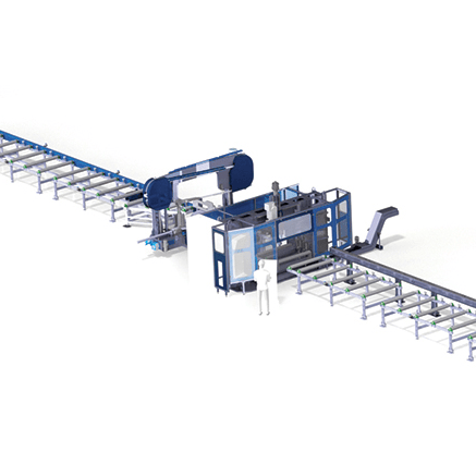
| Miter Band Saw Machine Integration | Optional | Optional |
| Weight | 13000 kgl | 11000 kg |
| Dimensions of the Machine | 2400*7000*200 mm | 2300*5400*3050 mm |
| D.O.T. Marking | Optional | Optional |
| Scribing Tool | On one side | On one side |
| Chip Conveyor | Standard | Standard |
Note:- Standard and optional accessories shown and mentioned are indicative. An offer will contain all aspects of supply. The above is only for an Idea.


